Installing EXTREME Motorcycle lights - ( Special thanks to Danie Malan for this informative piece) These powerful and elegant motorcycle lights greatly improve your safety in traffic (you are much more conspicuous when approaching other vehicles) as well as improving your safety when driving in the dark (any obstructions ahead are much more visible).
1 Installation of EXTREME Motorcycle lights with the Extreme Motorcycle Tubular Mount
Shown in Figure 1 below, is- an Extreme Mini Motorcycle Spot Light (2013 version), and
- an Extreme Tubular Mount (consisting of mount and screws)

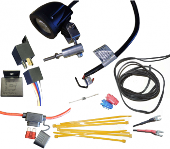
1.1 Components required (see Figure 2)
- EXTREME light with U-bracket (typically two units, one for each side of the motorbike)
- Tubular mounting with bolt and washers (one per light)
- Relay (12V as used in motor vehicles)
- Electric cable (copper to be at least 1 mm diameter)
- Skotch clamps (one red, one blue)
- Fuse holder with 1Amp fuse
- Diode (15Volt rating)
- Cable ties (4mm wide)
- Terminal slide clamps (one red and one black)
1.1 Tools required (see Figure 3)
- No 10 ring spanner
- 4mm Allen key
- Light thread locking fluid
- Soldering iron and solder
- Voltmeter (at least 12V DC)
- Heatshrink tubing (recommended above PVC isolation tape)
- Light pliers
- 1000mm length of light wire (dia 1mm or 2mm) or light line

1.1 Fitting the Tubular Mounting
The tubular mounting is based on the use of the M6 bolts that are used on many motorbikes to secure the body panels to the frame. The installation process is illustrated on a Honda TransAlp

The first step is to locate a suitable bolt to be used for securing of the tubular mounting.

Figure 5: Unscrew the M6 bolt, check presence of rigid support behind the panel[/caption] Unscrew the existing bolt and check that the rigid sleeve behind the body panel is present (see Figure 5). Pass the M6x40 cap screw through the spring washer and through the tubular mounting. Place a small amount of thread locking fluid on the bolt thread. Place the steel washer on the hole and thread the bolt home.
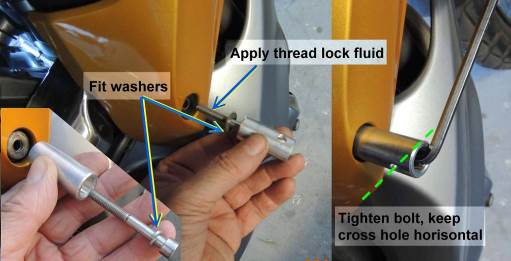
Figure 6: Secure the Tubular Mounting (note washers)
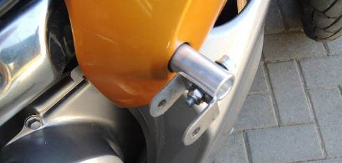
Figure 7: Secure the U-bracket

Figure 8: Secure the EXTREME light Repeat the procedure for the opposite side of the motorbike.
1 Electric circuit
1.1 Routing the electric wires
It is important to route the electric cables in such a way that they are safe and protected. Important factors to take into account:- Keep electric cables well clear of hot components such as the exhaust and the cooling system
- Route the electric cables such that the full length of the cable is protected from wind, stones and road damage by placing it behind body parts
- Allow enough slack on the cables in order to enable easy tie-down
- Solder all joints and isolate the joints properly with heat shrink sleeves
- Take extra care to properly mark positive and negative lines and terminations
Once you have decided which route the cables would run, use a string or light wire (Figure 9) and feed it through the intended route. Keep it in position because this may be needed later to pull the electric cables through the route.
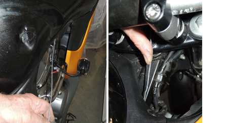
Figure 9: Find a suitable route for the electric cables
1.1 Placing the fuse
The fuse holder should be placed such that it is protected, out of the way yet easy to reach in case the fuse needs to be checked. See Figure 10. In many cases it is possible to place the fuse holder and relay switch close to each other.1.2 Placing the relay switch
The relay switch should be placed in a space where it is completely protected from rain and physical damage or displacement out of position due to vibration or road shocks. A typical safe position is within the frame below the fuel tank or below the seat. It is not very important to be able to reach the relay quickly/easily for maintenance.

Figure 10: Find a suitable position for the Fuse and Relay
1.1 Find a source for switching power
The power to the Relay Switch needs to be applied as soon as the headlight of the motorbike is switched on (and switched off when the headlight is switched off). For this reason the power line to the headlight is a very suitable point to connect the switching terminals of the relay. In addition, the current required by the relay solenoid is insignificant in relation to the high current supplied to the headlight.1.2 Length of the electric wires
The length of the electric wires is determined by the distance between the battery, the position of the relay and the distance to the source of the switching power (usually near the headlight).
2 Cable Make-up The basic circuit diagram is shown in Figure 11 below.
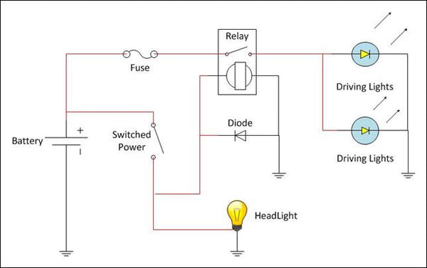 Figure 11: Circuit Diagram In practice, the completed circuit would be similar to that shown in Figure 12

Figure 12: Typical completed harness (dotted line is added for clarity)
Step 1 --- Relay switch Identify the appropriate terminals on the relay body. Effectively four pins are used. Two pins lead to the solenoid that closes the switch on the line that carries the load, two other pins carry the current through the switch that is operated by the solenoid. The solenoid normally has three pins on the power side: Normally Open and Normally Closed. The Normally Open contacts are used.
Step 2 --- Connecting the cables to the Relay Connect the cables as shown in Figure 13. An important feature is the inclusion of the diode. The purpose of the diode is to prevent reversed current surges when the current through the solenoid changes (power-on or power-off). Such reversed current surges may damage the electronics on CAN (Central Are Network) systems as found on most modern vehicles. The polarity of the diode is important, as well as proper insolation, as shown in Figure 13. Remember to slide the heat shrink tubes over the cables before soldering.
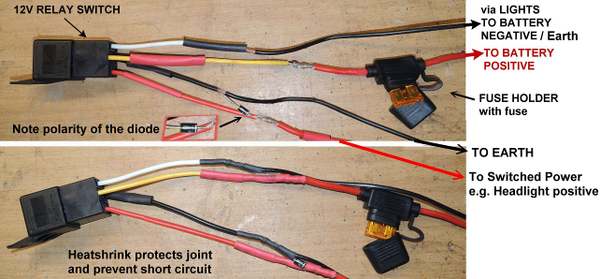
Figure 13: Soldering the diode The fuse is included to protect the battery and the general wiring of the motorbike, in case any short circuit that may arise in the circuit of the additional lights (eg in case of the motorbike falling over or a light or cable being damaged) The lines to the switching power usually need to be long (1m or more). See Figure 14. These lines are insulated at the relay and are untreated at the free end. The free ends will be connected to the harness of the motorbike using Skotch connectors and are therefor not treated. NB: Polarity is important and should be clearly marked at the free end.
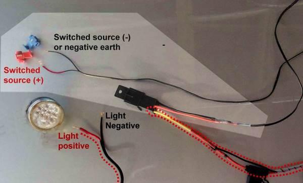
Figure 14: Switching cables
Step 3 --- Preparing the power cables As shown in Figure 15, the power cable that connects the battery to the lights is fitted with terminal slide clamps. The width of the opening should suit the battery terminal as fitted to your motorbike. Normally 8mm wide is sufficient.

Figure 15: Power cables
Step 4 --- Testing the harness It is advisable to test the harness before you install it onto the motorbike. First connect the power cables to a 12V battery (the motorbike battery can be used). Then attach the negative cable of the switch cable to the battery terminal. Touch the positive cable of the switching cable onto the positive terminal of the battery. The relay should make a click sound and the fuse should remain intact (a blown fuse indicates a short circuit, which has to be located and fixed) With the positive and negative switching cables connected to the battery, use the multimeter to check the polarity of the power cable. Red should be positive and black should be negative. If correct, remove the switching positive cable from the battery. Connect the Extreme lights to the power cable NB: ensure that the positive (red) line of the lights are connected to positive and the black line of the lights to negative (black) Incorrect polarity will blow the LEDs in the lights After successfully tested, the harness is ready to be installed onto the motorbike.
Step 5 --- Final installation on the motorbike Place the relay and fuse holder into the selected position. Feed the switching cables to the selected position where they will be connected. The light wire or string may be required to pull the end of the cable through the bodyparts of the motorbike. Feed the power cable to the battery and to the ends of the cables from the light units. Ensure that the cables do not pass near potentially hot parts such as the exhaust or cooling system. Connect the power cable to the ends of the cables from the light units and insulate the joints. Connect the switching cables to the selected wires, using the skotch clamps as shown in Figure 16.

Figure 16: Skotch clamps for connecting cables[/caption] Test the system by switching the headlight on and off.
Step 6 --- Securing the cables Finally, secure all loose parts of the cables to the frame and other convenient items, using light cable ties. Check that the lights point in the correct direction and are level. Check all bolts to be tight.